4-6 Introduction to RZ/G2L GPIOs
This chapter demonstrates how to test and develop programs to control the GPIO hardware pins on the Renesas RZ/G2L platform within a Linux environment. It covers using Linux Sysfs to manage GPIOs via file-based read/write commands.
Linux Sysfs
Sysfs is a pseudo-filesystem in Linux that provides a way to interact with kernel subsystems, hardware devices, and drivers via virtual files.
To read a file, use the following command:
cat filename
To write to a file, use:
echo xxx > filename
Accessing GPIO Pins
To access GPIO privileges on the RZ/G2L broad, navigate to /sys/class/gpio/ and export the desired GPIO pin ID:
echo gpio-pin-id > export
GPIO Pin IDs are calculated based on the port and pin as outlined in page 8 of Renesas GPIO documentation. For RZ/G2L, the formula is shown below:
GPIO ID = (Port Number * 8) + Pin Number + 120
For P42_4 (Port 42, Pin 4):
GPIO ID = (42 * 8) + 4 + 120 = 460
After exporting the pins, a directory named after your pin (e.g. P42_4) will be created under the /sys/class/gpio/ directory. Enter into the directory and use the command ls to list all the files.
The output will be:
active_low device direction edge power subsystem uevent value
Controlling GPIO Pins
To control GPIO pins, please ensure that you are in the sys/class/gpio directory.
Setting Pin Direction
echo "out" > direction
echo "in" > direction
Writing Values To Pin
echo 1 > value
echo 0 > value
Reading The Pin State
cat value
Hardware Testing Through PMOD Interface
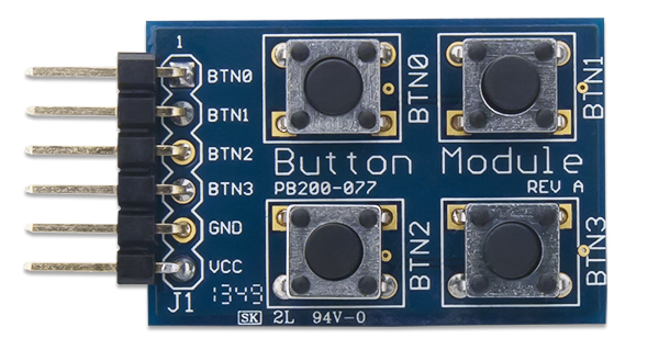
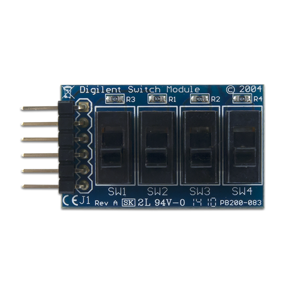
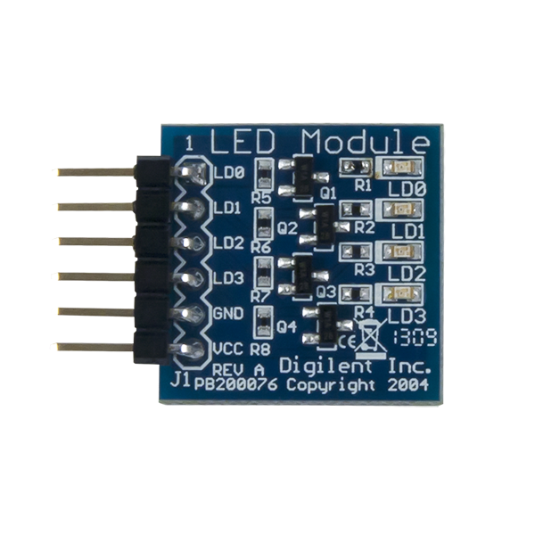
The PMOD (Peripheral Module) interface is a standardized connector used to interface peripheral modules with a host device, such as development boards, microcontrollers, or FPGAs. Developed by Digilent, PMOD connectors typically use a 6-pin or 12-pin header configuration, carrying signals such as power, ground, and data lines for SPI, I2C, UART, or GPIO communication. Designed for simplicity and flexibility, PMOD modules offer plug-and-play compatibility, enabling developers to easily add functionality like sensors, displays, and communication modules to projects without the need for complex wiring or additional circuitry.
Clone the GitHub repository below and build it in Qt Creator using the RZ/G2L kit.
git clone https://github.com/yourskc/q563_rzgpio.git
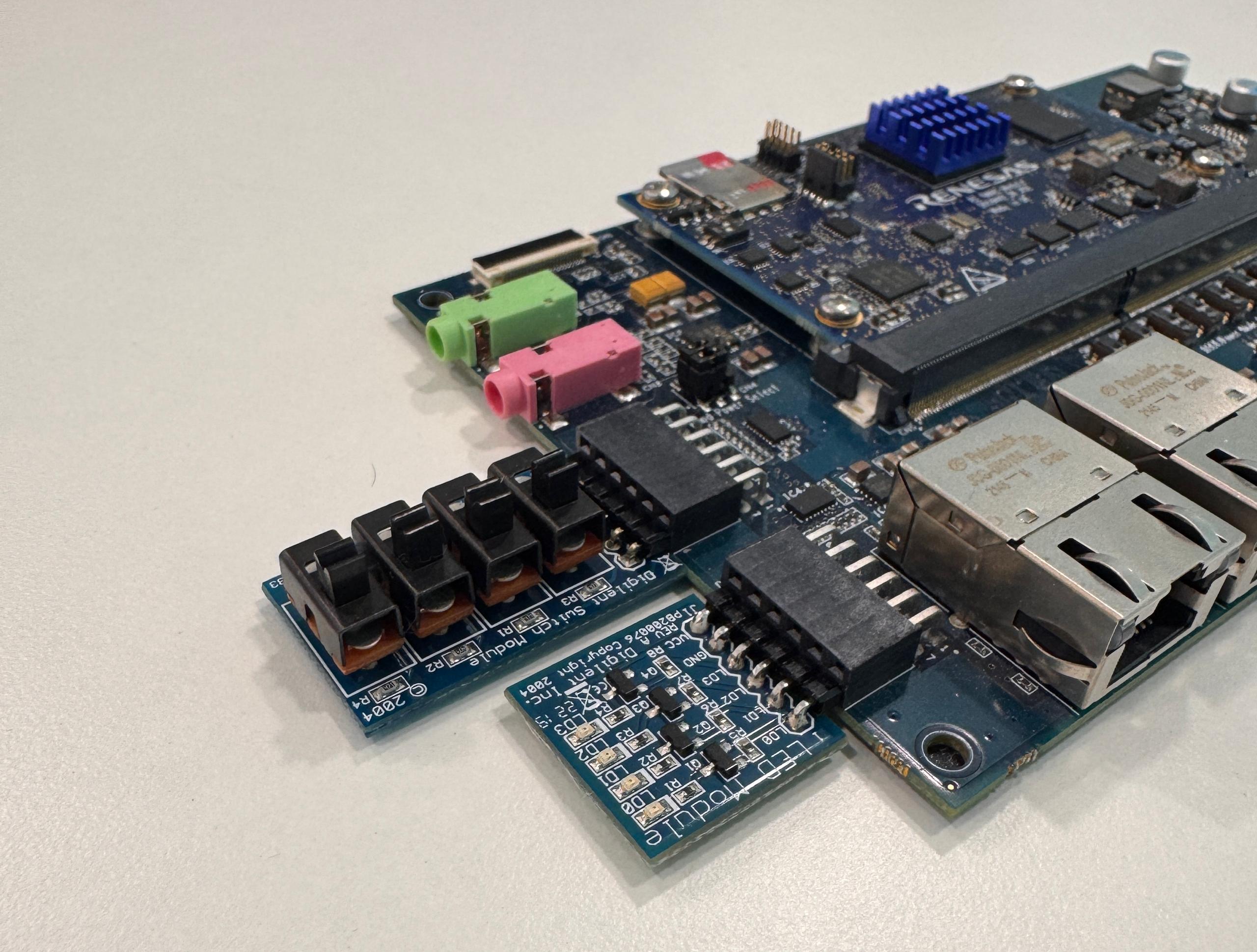
To match the configuration of the software program, please plug in the PMOD switch and LED according to the picture shown below. The PMOD switch should be connected to the 6 lower pins of PMOD1, and the PMOD LED should be connected to the 6 lower pins of PMOD.
Transfer the executable to RZ/G2L and run it. Try out the program and observe the output.